Brushless Drive and ESC Basics
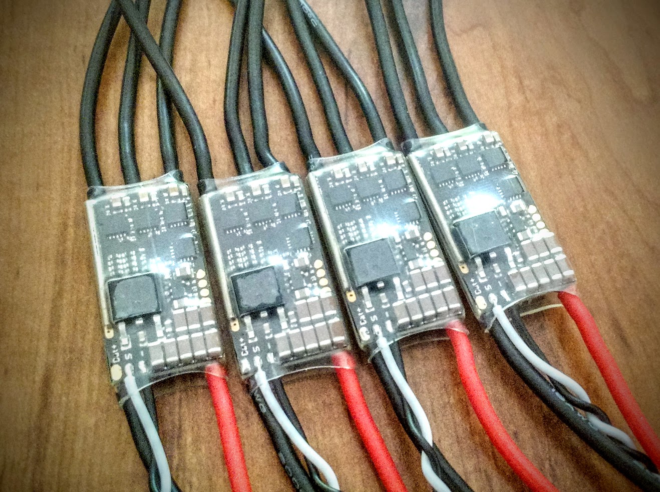
A brushless DC motor by itself is a relatively useless item. In reality it is only half of the equation to generate the mechanical energy that makes a mini-quad (or any brushless powered craft) move. For the purposes of this discussion I’m going to assume a certain base knowledge about how a 3 phase brushless motors achieves motion through the sequential magnetization of the phases in relation to the fixed magnets in the bell. We’re going to talk here in more detail about how that is achieved by the ESC, and how it impacts us as we combine motor and ESC.
Timing
While the motor bell is moving past the stators the non-active phase is being checked for the voltage level. As you know any magnetic field moving past a coil of wire creates a voltage in the wire that induces a current flow. As the non-active phases build up voltage from the motion of the motor, that voltage is measured by dedicated circuitry. The ESC can tell by how much voltage it is seeing on that line where the magnetic field of the bell is in relation to the phase being checked. In the ESC it is measured in degrees, though that is a virtual measurement, not a real angle. The assignment seems arbitrary, but it is related to the number of the phases in the motor. In the large majority of brushless motors there are three phases and two directions of current flow per phase, creating a total of 6 commutations. As a result, the ESC understands a measurement of 60 degrees (360 divided by 6) of magnetic field spanning from -30 to 30 degrees for each commutation. This voltage rise on the inactive phase is referred to as BEMF or Back Electro-Motive Force. Electro-motive force is simply another way of saying voltage, so really it just means back flowing voltage.
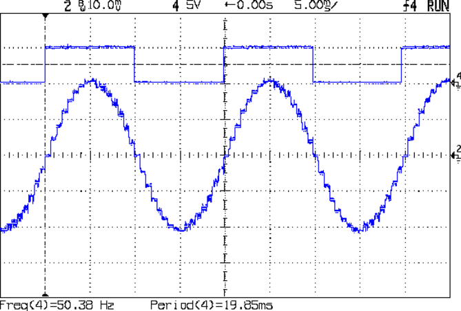 As the voltage rises from its lowest point at -30 degrees it progresses to its highest point at 0 degrees and then back down to 30 degrees as it leaves the phase. In the simplest form, the ESC measures the magnetic field of the bell as it passes the 0 crossing and uses that information to energize the coils at exactly the right point to pull the field around the bell without missing. If ESC loses track of where in the rotation the bell is moving, the coils can energize in a way that exerts force on the bell in the opposite direction of rotation rather than the forward direction. When the motor loses track of the bell, this is called a “dsync”, a term which most of us know well and dread equally! Each calculation of the 0 crossing and energizing of the coils in the motor is called a commutation, and commutations happen 6 times for each fixed magnet pair in the motor for each rotation. So for a 12N14P motor with 7 opposing pairs of poles (fixed poles divide by 2) there will be 42 commutations per physical rotation.
The tunable setting in the ESC that impacts this prediction is called motor timing or timing advance. What this setting changes is the amount of time after the 0 crossing is detected that the ESC begins to energize the coil. 30 degree timing advance means the coils start energizing immediately after the 0 crossing on the inactive phase is detected, and 0 degrees means the ESC waits for the full waveform to decay before it fires the next phase. Based on our earlier discussion of kV, we know what factors impact how long the coil takes to energize. The timing setting in on the ESC allows us to compensate for those differences between motors that change the time it takes for the coils to energize as well as the differences in the size and shape of the BEMF waveform to which the ESC needs to react.
There are a couple of good news items here, one being that timing is quite forgiving for the most part on brushless motors given the way commutations are calculated in the ESC. Going to a higher timing means the ESC fires earlier in the BEMF decay which means you will waste some current in the coils before it is doing mechanically much good but it also typically means that the field strength the coil is generating will be stronger by the time the bell magnetic field is approaching. This gives you a bit more torque and thrust at the expense of a bit of efficiency.
Going too low can mean that the ESC may actually miss the next phase, which can cause desync, but it can also gain some efficiency and cool the coils down a bit as less energy is lost as heat. Fortunately you have to go quite low before that is a problem.
Most of the recent strong magnet motors will do fine on medium timing but you'll get some small gains by going to medium high and you'll gain some resistance to desync. Generally speaking for most people medium high is probably the safest option across the board. That equates to 23 degrees advance in BLHeli_32. It is probably safe to run up to 25 degrees, but going above that will see minimal gains and larger increases in current. If you stick between 16 and 25 (medium to medium high) you should never have an issue with timing. If there is an issue, it is pretty much guaranteed it's not related to timing and is usually a flaw somewhere else in the system.
Some ESCs, namely the KISS ESCs and the new BLHeli_32 ESCs, support auto timing, which calculates the timing on-the-fly based on the BEMF waveform. While this is a good feature, it is often optimized for efficiency rather than power, so it can cost some performance on the top end in exchange for a bit of smoothness and some small efficiency gains.
Output PWM
Another piece of information we need to understand is how the ESC energizes the coils on the stator and achieves the drive mechanics. The ESC has series of FETs which are basically high current digital switches. The MCU on the ESC uses pulse width modulation (PWM) to control the switching of the FETs to allow current to flow to the phases of the motor in the correct order and correct polarity. PWM has two properties that we care about, frequency and duty cycle. Frequency denotes how often the MCU begins a pulse, and duty cycle refers to what percentage of the period (or maximum expected width) is “on” and what percentage is “off.” In BLHeli and BLHeli_S the PWM frequency is fixed based on the hardware for each ESC, but in BLHeli 32 the PWM frequency can be adjusted up to 48khz. Keep in mind this is output only between the MCU and the FETs (or in most cases the dedicated gate driver chip) and is completely different from and completely independent of input update frequency.
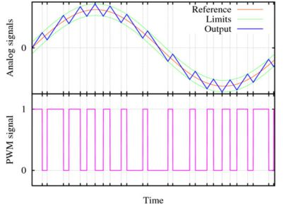 One of the interesting characteristics of PWM is that it actually acts as an analog simulation, essentially the same way a switching voltage regulator works to reduce the input voltage to a specified output voltage by chopping it up into smaller shorter pieces that average out to the lower voltage. Due to the properties of an inductor this also means that at low RPMs the BEMF waveform has very low amplitude, which can make it very hard to read.
At low throttle the PWM duty cycle between the ESC MCU and the FETs is very low, which simulates a low voltage. What we know from learning about the velocity constant (kV) we understand that as a result RPMs are low. As the throttle asks the ESC for more the MCU starts switching the FETS at a higher duty cycle which creates a simulated higher voltage, and resulting higher RPMs. Obviously based on our previous discussion of BEMF waves and timing, it's a lot more complex than that in actuality, but the functional outcome is a simulated analog voltage that is a certain percentage of the total battery voltage.
Demag Compensation and Startup Power
The Demag and Startup Power parameters that I want to look at next are unique to BLHeli-based ESCs, but are the cause of some confusion and a good number of questions.
The demagnetization prevention in BLHeli is really two components. Back in the original BLHeli days both functions were operated from just one variable, Demag Compensation. In BLHeli_S it was split in half. Half of the functionality went into a new variable that gave more fine tuned control and half stayed in the same old demag variable. The part that split out moved to the Startup Power variable.
In the original BLHeli, the Startup Power variable only impacted the 0 rpm start, or the transition from not-spinning to spinning. A few things we have discussed previously give us some clues as to the importance of this setting. The first thing we learned is that the BEMF waveform used to synchronize the motor drive comes from the magnetic field moving past the coil. When the motor is not spinning there is no waveform to be read, which means during startup the ESC has to essentially guess to get the motor moving enough to read the BEMF waveform. We also mentioned that at low RPMs the amplitude of the waveform is very low, which further complicates the startup. As a result, being able to tune how much power is given to the motor during that initial phase is quite critical. In our application, since the motor bells and props are so light, it is not as significant an issue, but you can see that as the rotational mass increases it becomes more and more challenging, which is where tweaking this value would really be necessary.
In BLHeli_S this setting was changed so that it impacts any rapid acceleration of the motor, not just during that initial start phase. Previously this part of the functionality was lumped in with demag, but only had two settings, low and high. In its current iterations in BLHeli_S, Startup Power limits the acceleration of the motor by limiting the maximum PWM duty cycle allowed based on the current running RPMs. The lower the RPMs, the less maximum power the motor is allowed to give. The Startup Power option changes the degree of power reduction applied. Generally speaking this happens so fast that it is not extremely noticeable to the pilot, but it may impact the tune some and could feel a bit sluggish on the very low settings. This setting can be left at default in the majority of cases, and should only be reduced if there is an issue. Most of the time reducing Startup Power is a bandaid for a large issue however, so relying on it as a permanent solution could be problematic.
In BLHeli_32 the Startup Power setting has been renamed to Rampup Power in an attempt to clarify the fact that it impacts all changes in speed from low RPMs and not just when the motor initially starts, but it keeps identical functionality. A new setting, Maximum Acceleration has also been introduced. Maximum Acceleration is a new function designed to compensate for the different ways kV can impact the relationship between RPMs and power. Rather than use a direct relationship between RPMs and power like the Rampup Power setting, Maximum Acceleration uses the rate of change of power to limit the acceleration. This is particularly necessary for large stator, low kV motors out of the range of our mini-quad applications, so this setting is not something we will need to adjust.
In all versions of BLHeli, Demag Compensation makes some small changes to the commutation methodology that helps recover from potential desync situations. The demag setting checks for the BEMF signal more rigorously for bad reading and will suspend energizing the coil of a commutation to make the next 0 crossing easier to detect. Demag Compensation will also attempt to drive the motor without readings similar to the method used when the motor is first starting up, using the last known RPMs to predict the phase positions. The high and low settings change the threshold that BLHeli uses or the number of bad BEMF reads that it is willing to accept before compensating, and turning it off means BLHeli will not attempt correct for bad readings at all. This functionality is the same in all revisions of BLHeli.
When setting demag to high you may loose some small power and acceleration due to the increased error checking and compensation, so generally speaking low is a good balance between desync resistance and responsiveness.
These settings came to focus in the early days of BLHeli_S when there were some hardware and software issues that made them necessary, but fortunately those issues are mostly long gone.
Braking
The advent of active braking on ESCs was probably one of the most significant developments in ESCs in mini-quad history. If you’re newer to the hobby and haven’t previously attempted to tune or fly a quad without active braking, you’re probably not aware of what a significant difference it made. Back in the Atmel days SimonK and BLHeli added the features within a few months of each other, and it revolutionized our flight experience.
When braking first came out there was a lot of questions about what exactly it was doing to brake the ESC. Before we can really start a discussion about the methodology it is important to understand that there are actually two types of braking that are common in ESCs. One is the brake to 0 RPMs or to a full stop, and the other when the motor is changing speeds from higher RPMs to lower RPMs. The two different types use two different methods to accomplish their goals.
Brake on Stop
First let’s look at the brake to full stop. This type of braking doesn’t really impact us in multirotors as there is really never any instance in flight where we would want to completely stop the propeller spinning. This method is more critical for gliders or hotliners that use a folding prop and want to be able to stop it spinning very quickly to allow it to fold up and reduce drag. The mechanism used by the ESC to accomplish this is very simple. If you’ve ever taken a brushless motor and held the wires of two phases together and tried to spin it, you’ve noticed a significantly increased drag. If you connect the wires from all three phases it gets even stronger. The current caused by the magnetic field moving past one phase feeds into the other phases which creates an opposing magnetic field of equal magnitude. This essentially means that the harder you attempt to spin the motor the more resistance it will have. This creates an extremely effective method of stopping the motor from spinning very quickly.
Essentially the ESC simply connects the phases together by closing the appropriate FETs between phases, and allows current to flow from one phase into the others while shutting off the power side of the ESC. This is very effective for this purpose but has very little control. It just stops the motor from spinning as quickly as possible. In early BLHeli this feature was combined with Damped Light mode, but in BLHeli_S and BLHeli 32 since Damped Light is no longer a configurable option this setting is called Brake on Stop. For multirotor pilots it only impacts how quickly the props stop spinning when you disarm. KISS ESCs do not have this feature at all and simply spin down with momentum on stop.
Complementary PWM (Damped Light) and Deadtime
The second type of braking that happens when RPMs are simply changing from higher to lower functions on a completely different mechanism. To understand what’s happening we need to look a bit at some of the terminology that is used to describe the braking. This method of braking is called Complementary PWM. In the old SimonK days the setting you needed was Comp_PWM, though BLHeli referred to it as Damped Light. This is also referred to as active or regenerative braking. All of these terms tell us something about how this functions.
To understand the mechanics of complementary PWM we first have to go back to our discussion of how the BEMF waveform is used to calculated the 0 crossing. The same technique that is used to detect the 0 crossing to drive the motor forward is used here, but in reverse. Instead of firing the phases in the order needed to drive the motor, the FETs for one of the phases are opened in reverse so that a temporary connection is made between phases but not connected to power. The electricity moving through the coils as a result of the magnets passing by creates an opposing magnetic field so that the magnetic field pulls on the bell instead of pushing. The strength and degree of the force exerted on the bell is controlled in the same way the acceleration is controlled because this connection is made during the inactive part of the actively driven PWM waveform. If the period of the PWM frequency is 20 microseconds (48khz) and the ESC input throttle (duty cycle) is 25%, then the two active phases would be connected to power for 4 microseconds and then connected to each other for 15 microseconds.
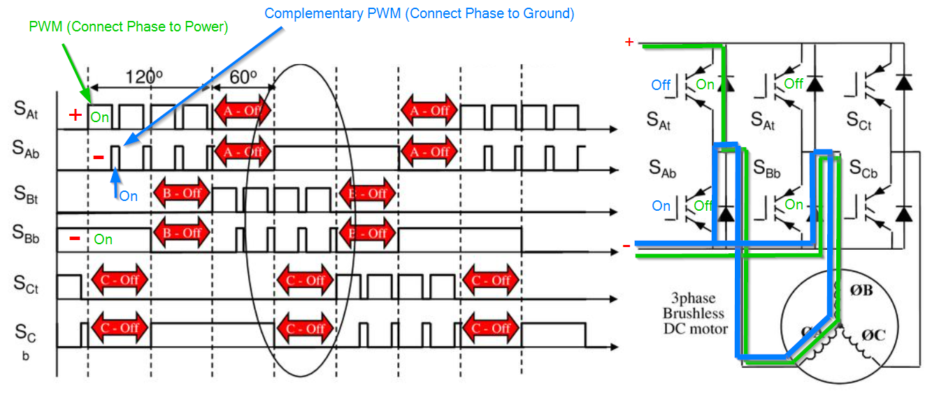
A byproduct of this method is that the magnets in the bell moving past the coils creates a magnetic field that actually turns the coil into a generator which accounts for a good deal of the drag on the system. The built up electrical potential has nowhere to go but to provide an opposing force to the motion of the magnets. As soon as the FETs switch to let current flow again, the built up potential results in a current flow back towards the battery. On the bench I have measured 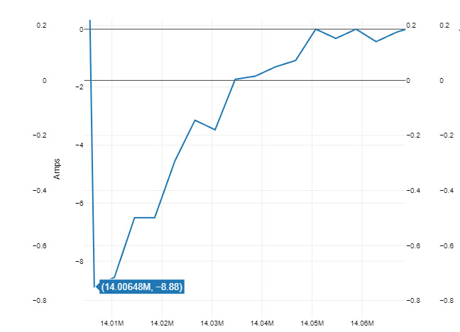 over 10A of reverse flowing current from only one motor, which means you can see over 40A+ in reverse if all 4 motors are strongly braking at the same time. This is why the term regenerative braking is used.
As we discussed earlier about the stator coils, the FETs in the ESC also have a rise time but in this case it has a larger impact on the ESC than it does on the motor. The rise time on a FET is the time between when MCU sends the signal and when current actually starts flowing through the closed switch. When the ESC is driving the motor it has to know how long to wait between switching the high (+) side and low (-) side of each phase for complementary PWM. If the switch for the low side closes before the switch for the high side fully opens you get something called shoot-through, which is essentially a dead short between positive and ground. As you can imagine this will fry an ESC extremely quickly, blowing one or both FETs on the phase.
The delay between switching the active and braked sides of the PWM cycle is called deadtime. The deadtime selection is constrained by the rise time on the FETs and circuit resistance between the gate driver and the FETs, and is usually assigned by detailed testing at the time the ESC is designed. A poorly designed drive circuit can impact dead-time as equally as a poor choice of FETs. The drive circuit must be precisely matched to the FETs used in the ESC. In BLHeli the deadtime was invisible to the end user but was hard coded into each firmware file for each ESC. In BLHeli_S it is the source of the last two digits in the firmware name (A_H_XX). In both cases the deadtime numbers are a multiplier to a base time period that defines how long the ESC should wait between switching FETs on the phase.
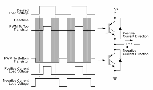 You typically don't want to change the deadtime multiplier as it is a fixed value for a specific ESC, but if you are getting very hot ESCs it is generally ok to go higher, but never ok to go lower on the deadtime multiplier. Some ESCs pass handling of the deadtime off to the dedicated gate driver chip (defined by the 00 deadtime multiplier.) Some of the drivers support true auto deadtime based on internal calculations (KISS and the TBS Bulletproof ESCs to name a few), but often the "auto" deadtime just means that the deadtime value has just been hard-coded in the gate driver.
As of yet I have not seen a significant performance difference between ESCs with low deadtime, and those with higher deadtime. The primary outcome is likely to be a slight increase in smoothness on ESCs with lower deadtime and a measurable increase in braking force depending on the PWM frequency, though theoretically there could be some efficiency and power gains on ESCs with a well designed drive circuit, high quality FETs and a resulting fast switching frequency and very low deadtime. As we go up in PWM rate, lower deadtime also becomes more important and will show larger gains in braking, as deadtime becomes a larger percentage of the available period for braking.
Since they are somewhat similar in function it can be confusing to differentiate between motor advance timing and deadtime in the ESC. The core of what you need to remember is that deadtime handles the ESC side and timing handles the motor side.
Conclusions
Fortunately most of the improvements in ESC technology have been largely transparent to the end user. On the majority of setups, stock ESC settings should not give you any trouble. The only change I would recommend is possibly moving timing from medium to medium high to gain a small performance boost and slight resistance to desync. If changes are made, be aware that anything that shifts the acceleration or power output of the motor is likely to cause a need to adjust the tuning of your quad.

